KUKA robots
RoboDK supports all KUKA robot controllers since KRC2, including KUKA KRC3 and KRC4 controllers. This documentation is based on a KRC4 controller.The KRC4 robot controller runs the Microsoft Embedded Windows 7 operating system. Previous controllers, such as KRC2, run Windows 95. The robot teach pendant shows an “HMI” which is a program that KUKA developed to run on Windows and it is the interface that the robot user must use manipulate the robot.
The following sections demonstrate typical operations using a KUKA robot teach pendant to prepare a new program in RoboDK and transfer it to the robot.
Follow these steps to load a program form a USB disk to your KUKA KRC4 robot controller.
1.Insert the USB disk on the robot controller (it is much faster than using the teach pendant connection)
2.If we don’t see the USB disk we must enter inAdministratormode
3.Select the file from the USB disk
4.SelectEdit➔Copy
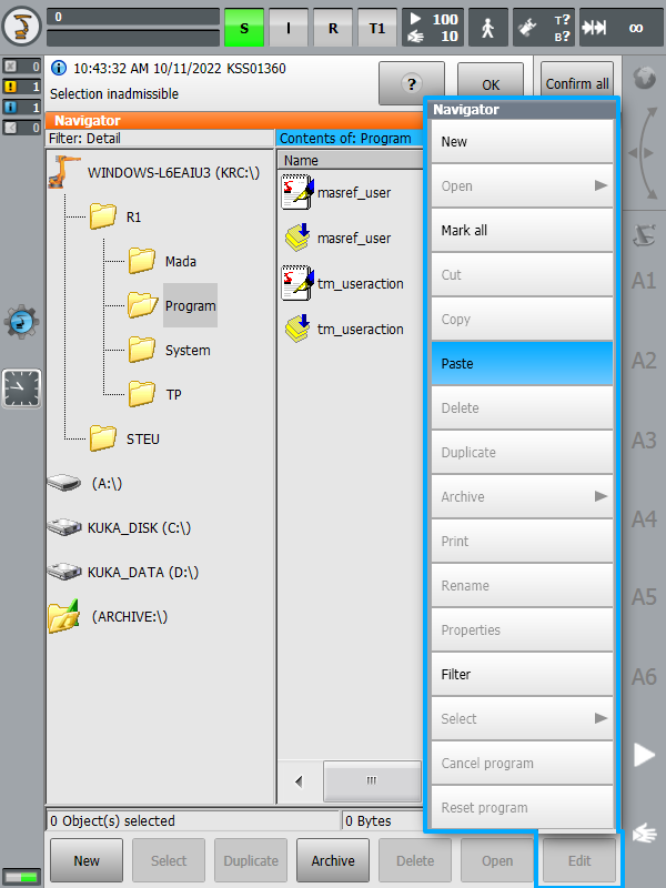
5.Select a folder in the KRC unit
6.SelectEdit➔Paste

当生成机器人程序库卡机器人的方式呈现controllers you can define the coordinate systems ($BASE) and tools ($TOOL) given the same coordinates you entered in RoboDK or numbered coordinate systems and numbered tools respectively.
By default, RoboDK exports the full pose (XYZABC values) of your tool and coordinate system the same way you entered them in RoboDK. The following code shows an example of what RoboDK generates for a KUKA SRC robot program:
; ---- Setting tool (TCP) ----------
; TOOL_DATA[3]={FRAME: X 116.058,Y 0.0,Z 219.481,A 0.0,B 60.0,C 0.0}
$TOOL = {FRAME: X 116.058,Y 0.0,Z 219.481,A 0.0,B 60.0,C 0.0}
; $TOOL=TOOL_DATA[3]
; ----------------------------------
; ---- Setting reference (Base) ----
; BASE_DATA[1]={FRAME: X 640.289,Y -290.0,Z 0.0,A 90.0,B 0.0,C 0.0}
$BASE = {FRAME: X 640.289,Y -290.0,Z 0.0,A 90.0,B 0.0,C 0.0}
; $BASE = BASE_DATA[1]
; ----------------------------------
On the other hand, if you prefer linking your tool ($TOOL variable) and coordinate system ($BASE variable) to numbered tools and reference frames, you can change the following variables in your post processor:
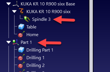
·FRAME_INDEX: Set this variable to True to link your coordinate system to a numbered base frame. You should make sure your reference frame has a number in your RoboDK station as shown in the following image.
·TOOL_INDEX: Set this variable to True to link your tool to a numbered tool. You should make sure your tool has a number in your RoboDK station as shown in the following image.
Follow these steps to start a robot program on your KUKA KRC4 controller.
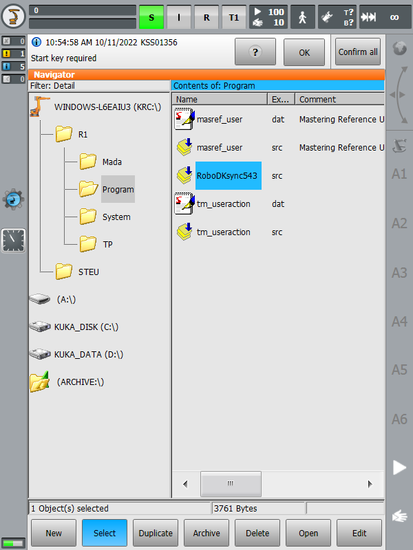
1.Select a program from the KRC memory unit
2.SelectSelecton the screen
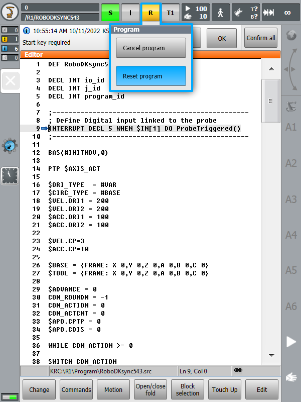
3.Select the button “R” (top) andReset program
4.Start the program by selecting green “Play” button on the teach pendant
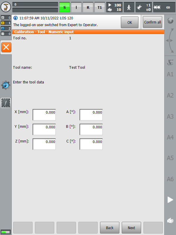
The following steps allow you to create or modify robot tools (TCP) from your robot controller, also known as$TOOLin KUKA KRC robot programming):
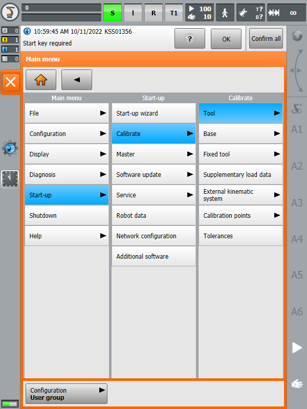
1.Select![]() KUKA➔Start-up➔Calibrate➔Tool
KUKA➔Start-up➔Calibrate➔Tool
2.Select a tool and edit or retrieve the X,Y,Z position of the TCP.
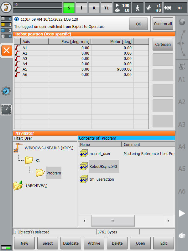
The following steps allow you to retrieve the robot joints from your robot:
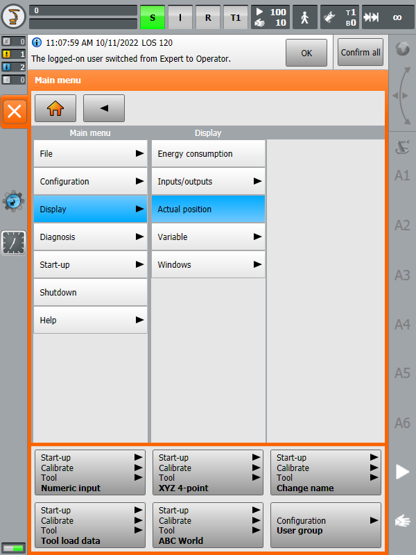
1.Select![]() KUKA➔Display➔Actual position
KUKA➔Display➔Actual position
2.SelectJointsmode and use the left column to take the robot joints
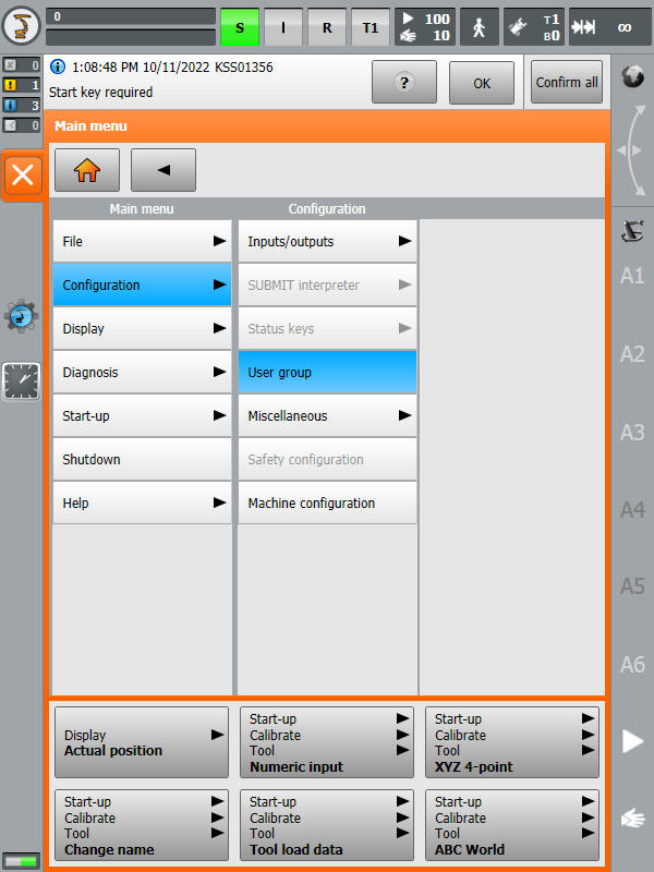
Some menu sections require “Expert”or“Administrator” rights. The following steps allow entering in “Expert” mode:
1.Select![]() KUKA➔Configuration➔User group
KUKA➔Configuration➔User group
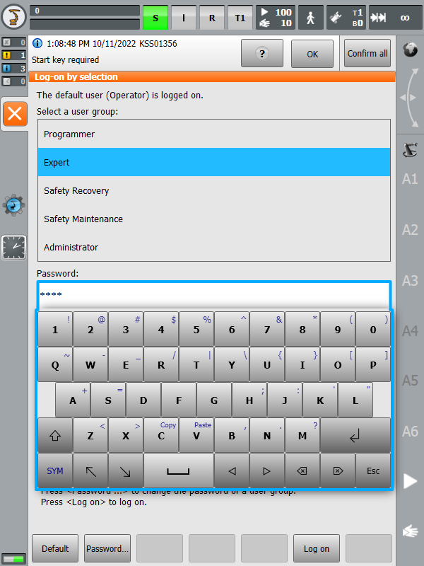
2.SelectExpert(orAdministrator).
3.Enter the password if required (the default password is “kuka”)
机器人司机提供线下公关的替代品ogramming (where a program is generated, then, transferred to the robot and executed). With robot drivers, it is possible to run a simulation directly on the robot (Online Programming). More information available in theRobot Driverssection.
You can establish a connection between RoboDK and your KUKA controller to move the robot automatically from your computer. This allows using the RoboDKRun on robotoption for online programming and debugging. The connection can be established through a standard Ethernet connection (TCP/IP).
If you don’t use a recent version of the RoboDK you may be using the legacy driver (apikuka, based on the KUKAVARPROXY project). To use the current driver, make sure that thekukabridgedriver is selected in theMore optionssection of theConnection to Robotwindow.

Follow these steps to set up the RoboDK driver for KUKA:
1.Get theC3 Bridge installerfile (c3setup executable) from thedriver sectionor by contacting us.
2.Using the KUKA HMI, copy thec3setup.exeinstaller file to the desktop of your controller or a folder of the control system.
3.Connect a mouse (optional, but strongly recommended).
It is possible to plug USB devices to the teach pendant or the controller (reboot is not required).
Alternatively, it is possible to establish a remote desktop connection.
These steps can also be accomplished using the teach pendant’s touch screen and the virtual keyboard.
4.Using the KUKA HMI application it is possible to open the main menu using the KUKA button![]() , at the top left of the screen:
, at the top left of the screen:
a.![]() KUKA➔Configuration➔User group➔chooseExpert(password:kuka)
KUKA➔Configuration➔User group➔chooseExpert(password:kuka)
b.![]() KUKA➔Start-up➔Service➔Minimize HMI(the windows screen will appear)
KUKA➔Start-up➔Service➔Minimize HMI(the windows screen will appear)
5.Locate the previously copiedc3setup-1.6.1.exefile and run it. Follow the instructions of the installer.
6.Allow port7000(or another port if port7000is busy, see note below)for TCP/UDP communication (this step is not required on KUKA KRC2 controllers):
a.Restore the HMI.
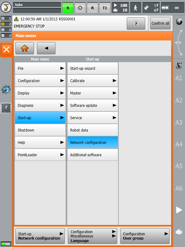
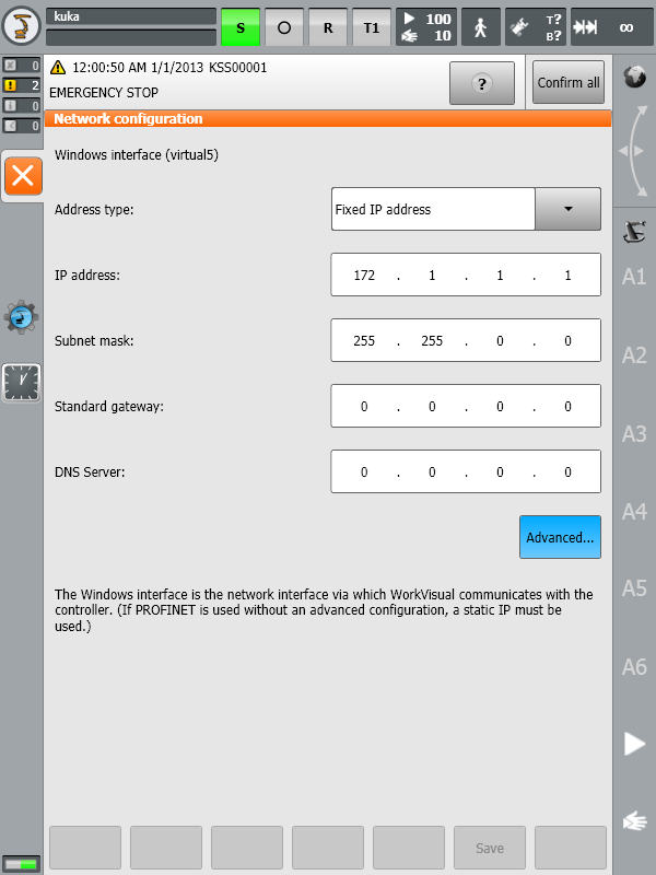
b.![]() KUKA➔Start-up➔Network configuration➔Advanced
KUKA➔Start-up➔Network configuration➔Advanced
c.NAT➔Add port➔Port number7000
d.Set permitted protocols:tcp/udp
7.LaunchtheC3 Bridge Serverfrom the desktop shortcut or the Start Menu item (you can skip this step in case you selectedRun C3 Bridge Serverat the last installation step).
8.To start C3 Bridge Server automatically at system startup, copy the application shortcut from the desktop to the Startup folder of the StartMenu.
The C3 Bridge Server is now ready. You can leave this program running. This server allows you to exchange global variable values between the KUKA control system and the remote PC, download and upload KRL programs, control the execution of KRL programs, and more.
Further configuration of the control system can be done in two ways: automatically using the interactive mode of thekukabridgedriver (KRC4 only) and manually by editing the robot control system files in KUKA HMI. Let's take a look at both approaches.
The scriptKUKA_Auto_Configuration.pyin the folderC:\RoboDK\Library\Scriptscan be used to perform automatic configuration of the KUKA control system. In that case, the current RoboDK station must contain at least one KUKA robot with the correct IP address and port in theConnection to Robotwindow. The script can be called from the menuTools➔Run Scriptor by theShift+Shotkey.
Prerequisites:RoboDK version 5.5.2 or higher, Windows operating system, installation pathC:\RoboDK.
1.Open command shell withSTART➔All programs➔Accessories➔Command Prompt
orSTART➔Run➔cmd.
2.Change directory toC:\RoboDK\binand launchkukabridge.exeby executing following commands:
c:
cd C:\RoboDK\bin
..\api\Robot\kukabridge.exe
3.Now KUKA Bridge Driver is running in interactive mode.
4.Establish a connection to the control system by enteringCONNECT
CONNECT 172.1.1.10 7000 6
5.If successful, you will see the following output:
SMS:Connecting
Connected
SMS:Working...
SMS:Ready
6.Request current robot joint position by typing theCJNTcommand:
CJNT
SMS:Working...
JNTS 0.00000 0.00000 0.00000 0.00000 0.00000 0.00000 0.00000 0.00000 0.00000 0.00000 0.00000 0.00000
SMS:Ready
7.Perform automatic configuration with theCONFIGURE FORCEcommand:
CONFIGURE FORCE
SMS:Working...
Requesting robot program state
Current robot program state is #P_FREE
Reading current configuration ($config.dat)
Read complete, updating configuration
Adding definition of variable COM_ACTION
Adding definition of variable COM_ACTCNT
Adding definition of variable COM_ROUNDM
Adding definition of variable COM_VALUE1
Adding definition of variable COM_VALUE2
Adding definition of variable COM_VALUE3
Adding definition of variable COM_VALUE4
Adding definition of variable COM_E6AXIS
Adding definition of variable COM_FRAME
Adding definition of variable COM_POS
Adding definition of variable COM_E6POS
Configuration lines have been updated: 11 added, 0 removed, 0 updated, 659 total
Checking existence of old backup file ($config.bak)
Old backup file exists, deleting it
Creating new backup file ($config.bak)
Backup completed, writing new configuration
New configuration was successfully written
Checking existence of program file (RoboDKsync543.src)
Program file does not exists
编写程序文件的机器人系统
Configuration is complete
SMS:Ready
8.Now your robot is ready to work, all you have to do isselect and run the programRoboDKsync543.src.
The next steps are to manually set up the main program that will handle the robot movements:
1.Add the declaration of the following global variables:
To do so, locate and modify the file “KRC:\R1\SYSTEM\$CONFIG.DAT” via KUKA HMI. The folder “KRC:\R1\” can also be accessed from theC:\drive at the following Windows path: “C:\KRC\ROBOTER\KRC\”.
INT COM_ACTION=0
INT COM_ACTCNT=0
REAL COM_ROUNDM=0
REAL COM_VALUE1=0
REAL COM_VALUE2=0
REAL COM_VALUE3=0
REAL COM_VALUE4=0
DECL E6AXIS COM_E6AXIS
DECL FRAME COM_FRAME
DECL POS COM_POS
DECL E6POS COM_E6POS
2.Copy the KUKA SRC programRoboDKsyncVER.srcto the folderKRC\R1\PROGRAM. TheVERsuffix in the file name denotes the version of the program (for example,RoboDKsync543.src).
3.Manually start theRoboDKsyncVER.srcprogram to make the robot listen for commands coming from the computer.
If theRoboDKsyncVER.srcprogram is not running, RoboDK will still be able to read the robot joints if the C3 Bridge Server is running in the robot controller.
The legacy KUKA driver is calledapikukaand is used in conjunction with KUKAVARPROXY. This solution is now obsolete and is being discontinued by RoboDK. If you want to use this driver, make sure it is selected in theMore optionssection of theConnection to Robotwindow.
Follow these steps to set up the legacy driver for KUKA:
1.Connect a mouse (optional, but strongly recommended).
It is possible to plug USB devices to the teach pendant or the controller (reboot is not required).
Alternatively, it is possible to establish a remote desktop connection.
These steps can also be accomplished using the teach pendant’s touch screen and the virtual keyboard.
9.Using the KUKA HMI application it is possible to open the main menu using the KUKA button![]() , at the top left of the screen:
, at the top left of the screen:
a.![]() KUKA➔Configuration➔User group➔chooseAdministrator(password:kuka)
KUKA➔Configuration➔User group➔chooseAdministrator(password:kuka)
b.![]() KUKA➔Start-up➔Service➔Minimize HMI(the windows screen will appear)
KUKA➔Start-up➔Service➔Minimize HMI(the windows screen will appear)
10.Copy the KUKAVARPROXY folder on the Desktop (or somewhere in the controller PC)
11.Allow port 7000 for TCP/UDP communication (this step is not required on KUKA KRC2 controllers):
a.Select the HMI.
b.![]() KUKA➔Start-up➔Network configuration➔Advanced
KUKA➔Start-up➔Network configuration➔Advanced
c.NAT➔Add port➔Port number 7000
d.Set permitted protocols:tcp/udp
12.Start the KUKAVARPROXY.EXE program on the robot controller (running on Windows).
13.The following steps allow starting the driver automatically on the controller on reboot (recommended):
a.Create a shortcut of theKUKAVARPROXY.EXEfile
b.Select WindowsSTART➔All programs➔Right click startup➔Open
c.Paste the shortcut in the startup folder
The KUKAVARPROXY server is now ready. You can leave this program running. This server allows exchanging global variables from the KUKA controller to the remote PC.
The next steps are to set up the main program that will handle the robot movements:
1.Add the declaration of the following global variables:
To do so, locate and modify the file “KRC:\R1\SYSTEM\$CONFIG.DAT” via KUKA HMI. The folder “KRC:\R1\” can also be accessed from theC:\drive at the following Windows path: “C:\KRC\ROBOTER\KRC\”.
INT COM_ACTION=0
INT COM_ACTCNT=0
REAL COM_ROUNDM=0
REAL COM_VALUE1=0
REAL COM_VALUE2=0
REAL COM_VALUE3=0
REAL COM_VALUE4=0
DECL E6AXIS COM_E6AXIS
DECL FRAME COM_FRAME
DECL POS COM_POS
DECL E6POS COM_E6POS
2.Copy the KUKA SRC programRoboDKsyncVER.srcto the folderKRC\R1\PROGRAM. TheVERsuffix in the file name denotes the version of the program (for example,RoboDKsync543.src).
3.Manually start theRoboDKsyncVER.srcprogram to make the robot listen for commands coming from the computer.
If theRoboDKsyncVER.srcprogram is not running, RoboDK will still be able to read the robot joints if the KUKAVARPROXY program is running in the robot controller.
您应该能够使用the driver with KUKA robots even when you use external axes. On the other hand, it is recommended to use a numbered coordinate system or a coordinate system you have defined on your robot controller. By following this procedure, you don’t need to perfectly match the kinematics of your external axes in RoboDK.
For example, to be able to use the RoboDK driver by default, the kinematics of your external axes defined in the robot controller should match the kinematics created in RoboDK. Also, if you have a turntable, the root point of the turntable should match the position of the turntable defined in RoboDK.
Follow these steps to use the driver using a known coordinate system:
1.SelectTools➔Options➔Driverstab.
2.Check the optionProvide Cartesian coordinates with respect to the reference.

3.Replace the$BASEvariable of yourRoboDKsynch.srcprogram file by the coordinate system you want to use.
For example, if you want to use the base reference frame number 5, the RoboDKsync.src file should look like this (the first line is commented, you should find it around line 25):
; $BASE = {FRAME: X 0,Y 0,Z 0,A 0,B 0,C 0}
$BASE = BASE_DATA[5]
This coordinate system must have been defined in the KUKA robot controller and RoboDK will not override this value.
You can use RoboDK to calibrate KUKA robots that have already been calibrated by KUKA using the Absolute Accuracy option. However, you should make sure to deactivate this option in the KUKA robot controller. When you calibrate a KUKA robot that has already been calibrated by KUKA using the Absolute Accuracy option it is important to deactivate this option so you can calibrate it using RoboDK.
To deactivate KUKA’s Absolute Accuracyyou should set variableDEACTIVATE_ABS_ACCURtoTRUE. You can find this variable in the fileKRC:\STEU\MADA\$custom.dat(around line 73).
You can make sure that KUKA’s absolute accuracy option has been properly deactivated by moving the robot to a known position (for example, move the robot axes of the real robot and in RoboDK to the home position) and make sure the Cartesian position displayed by the robot controller matches the same Cartesian position displayed by RoboDK.